
Before We Begin:
Disclaimers
This document covers the DIY installation of the Dual Frequency Oscillator in a VA1 Sega Saturn console. Mobius Strip Technologies or any of it’s associates cannot be held responsible for any damage that occurs from the improper installation of this device. It is expected that the person performing this installation has the necessary tools and knowledge to safely do so. If you are not comfortable with electrical circuits, discharging capacitors, using basic hand tools, soldering, or working with electronic devices with high ElectroStatic Discharge sensitivity, please stop now and consult a qualified technician. You have been warned.
- It is expected that you already know how to open your Saturn console. If you are unfamiliar with this process, please seek out tutorials on disassembling your Saturn console. Please note that the documentation for this modification will feature images from Saturn VA1 only. While compatible with other systems, some components may have different designations or locations. Please consult a service manual if you are unsure.
- On the main board locate the Crystal. As seen in the red box below.
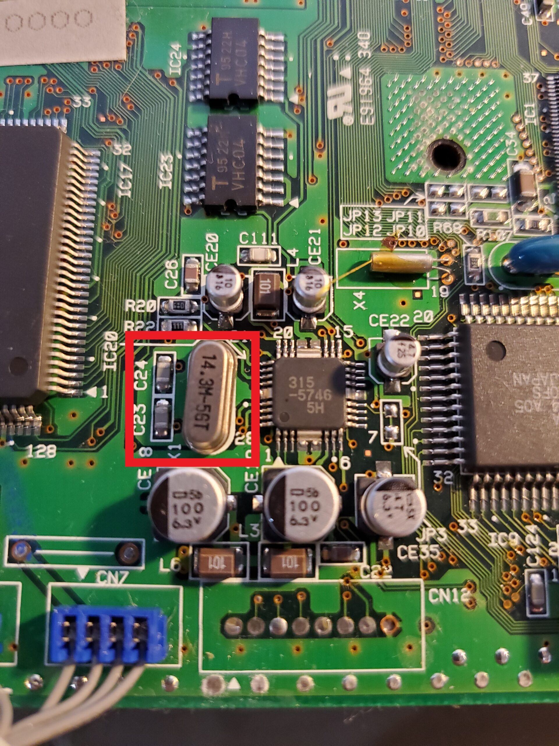

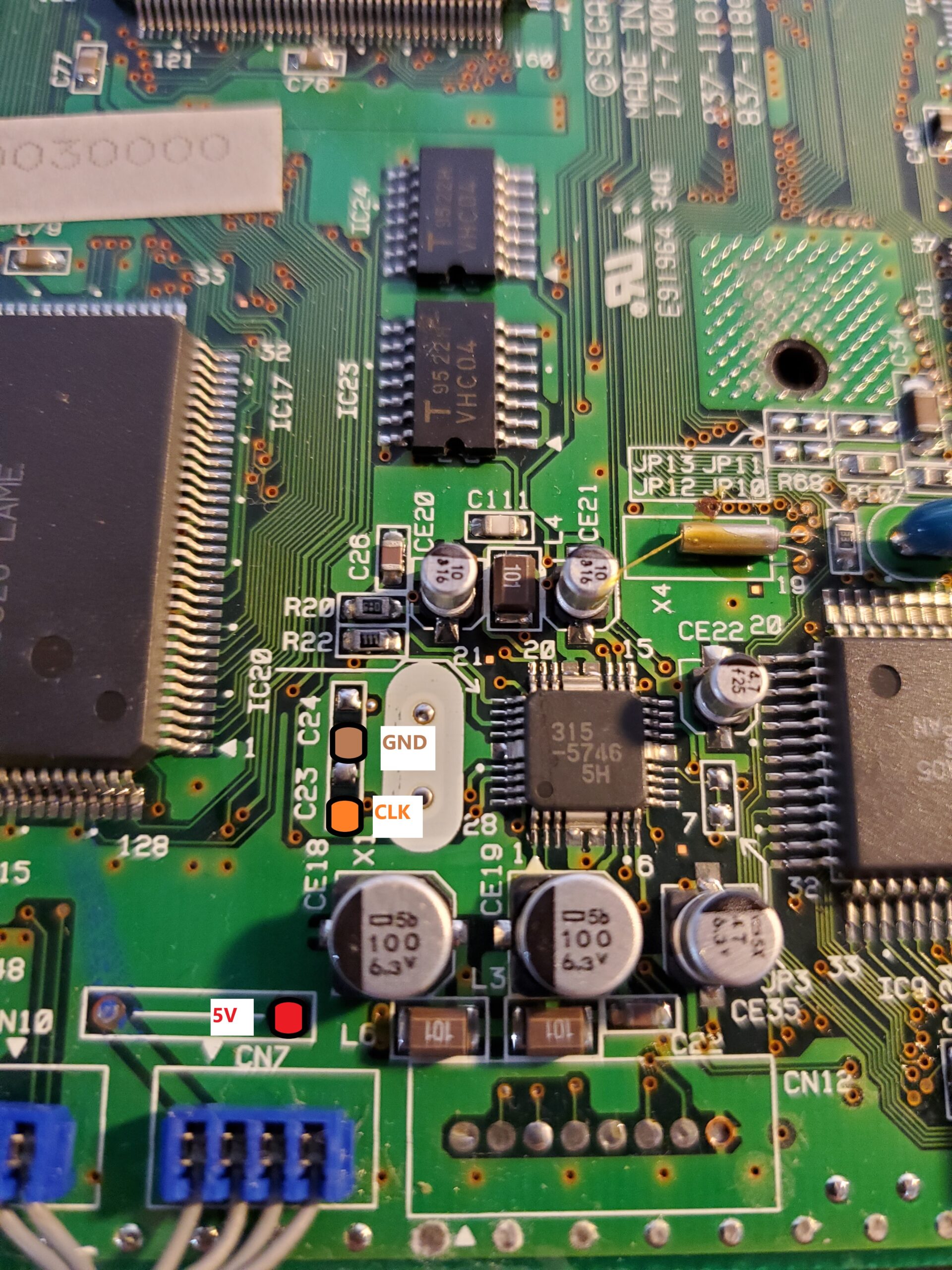
- The Crystal and 2 capacitors will need to be desoldered from the mainboard. The points shown below will need to be connected to the corresponding points on your DFO board.
- With the DFO now connected to the points previously used for the Crystal. You will have the S0 pad unconnected on the DFO board. Currently your console is either NTSC or PAL. However with the DFO you have the option to change that and also make it switchable. To do this locate the JP1 and JP2 jumpers on your console. They may be on the underside of the board.
Note this system was a US NTSC and so there is a small trace connecting the pads of JP1. If your system is a PAL unit, then JP2 will have this trace instead.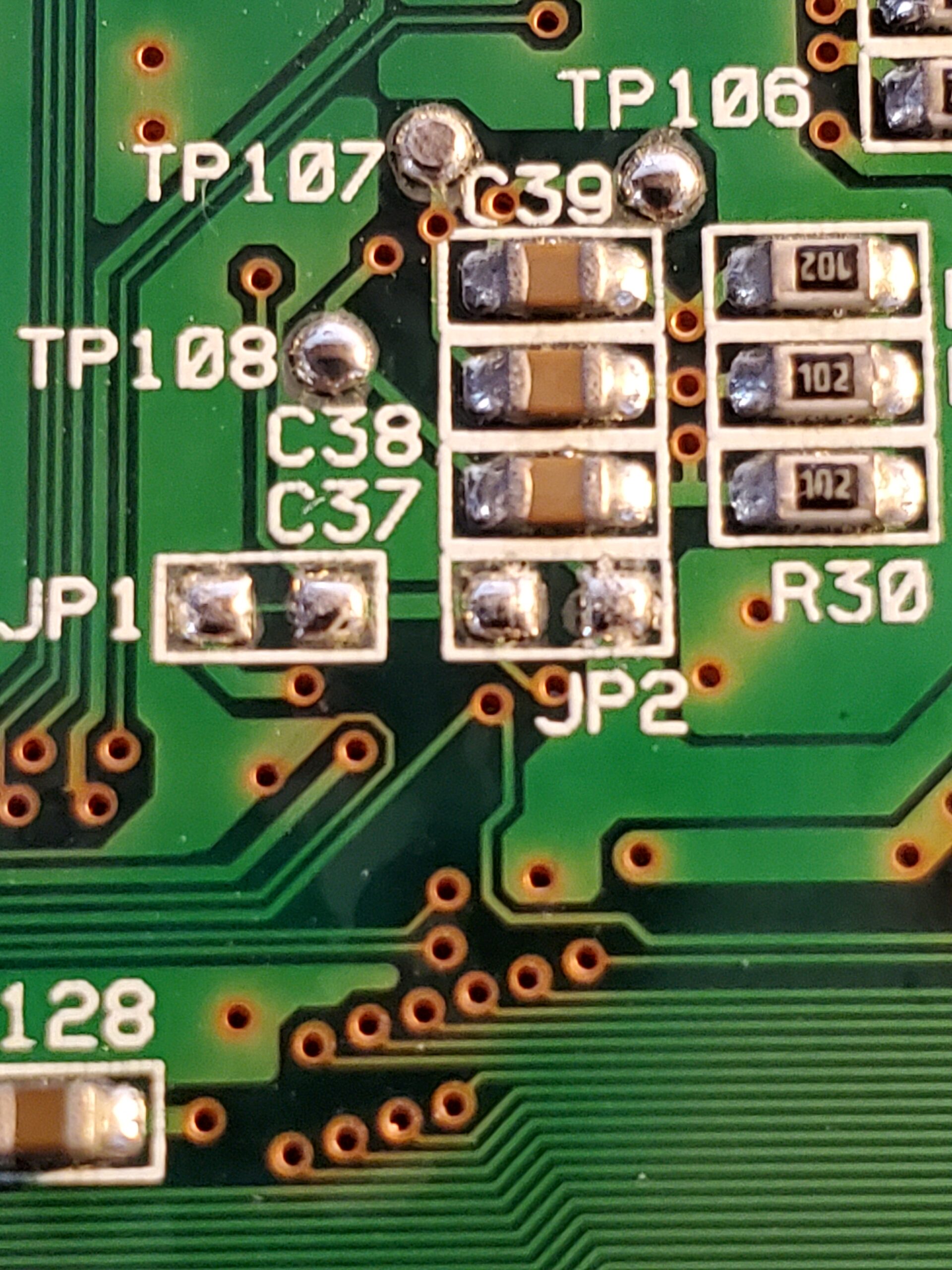
- Sever the trace or desolder the jumper, if it is soldered. This will put the system into an “open region” mode. Meaning it will need to be set by an external connection.
If you intend on locking the system as either PAL or NTSC, then you can bridge the pads of JP1 for NTSC or JP2 for PAL. Then connect the DFO S0 pad to 5v for NTSC or Ground for PAL and you are done.
If you don’t want the system permanently set to one of these two, then leave these pads alone after severing the trace and continue to step 6.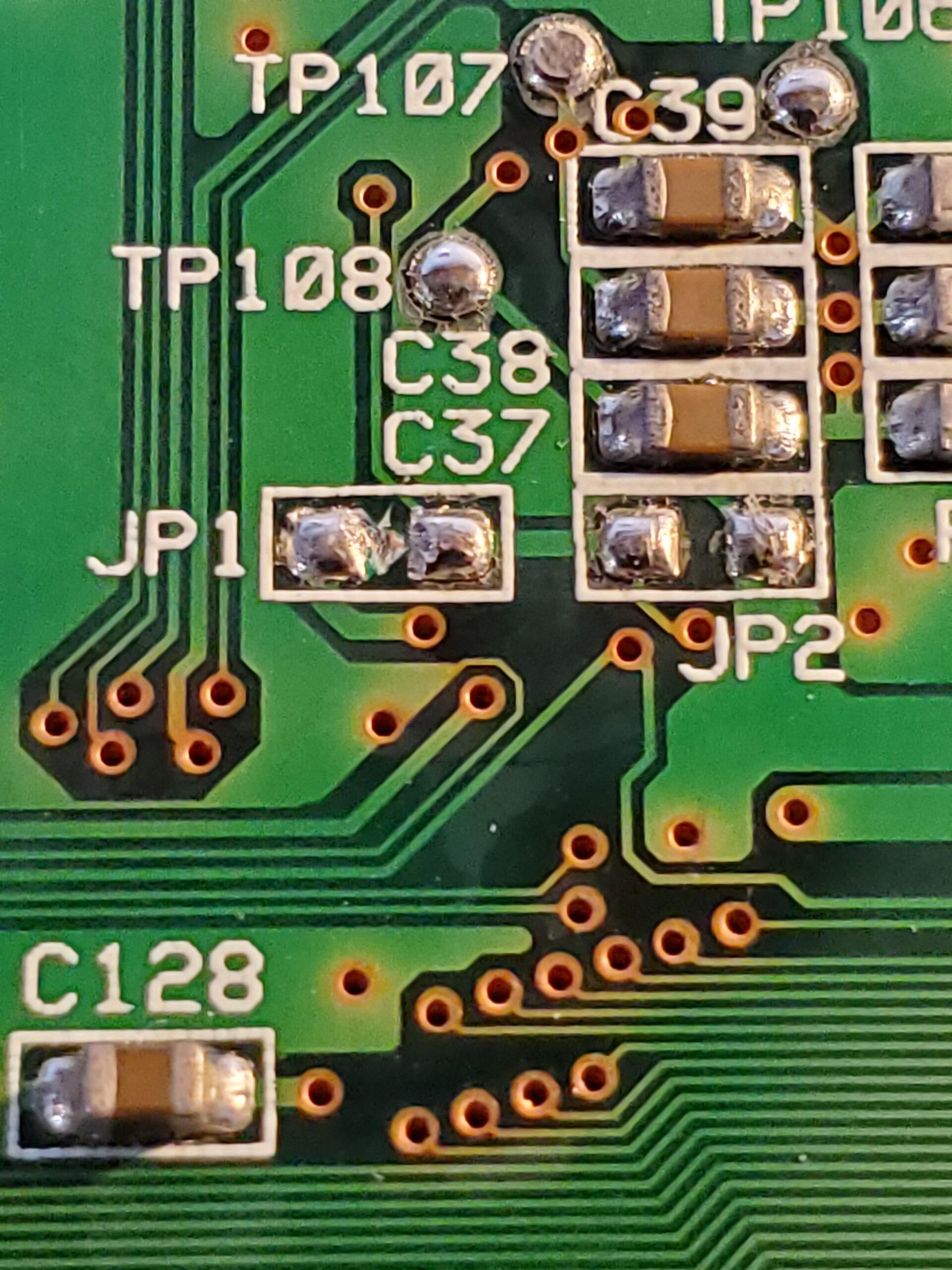
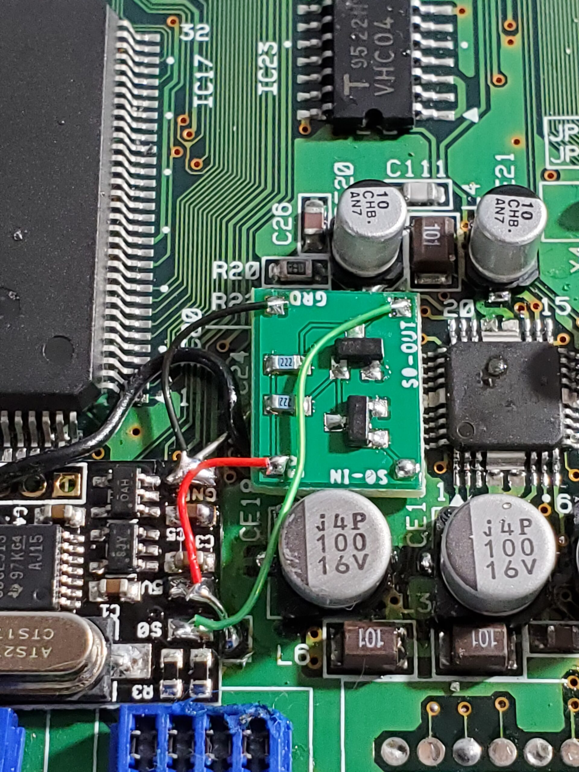
- Now that you have the connections severed, it’s time to install the adapter board. The adapter board can be installed near your DFO or in a different position if needed. On the adapter board you will need to connect 5v, Ground, and the S0-Out pad to the DFO board as shown below. You may also connect the 5v and Ground connections to other points, but this is generally easiest.
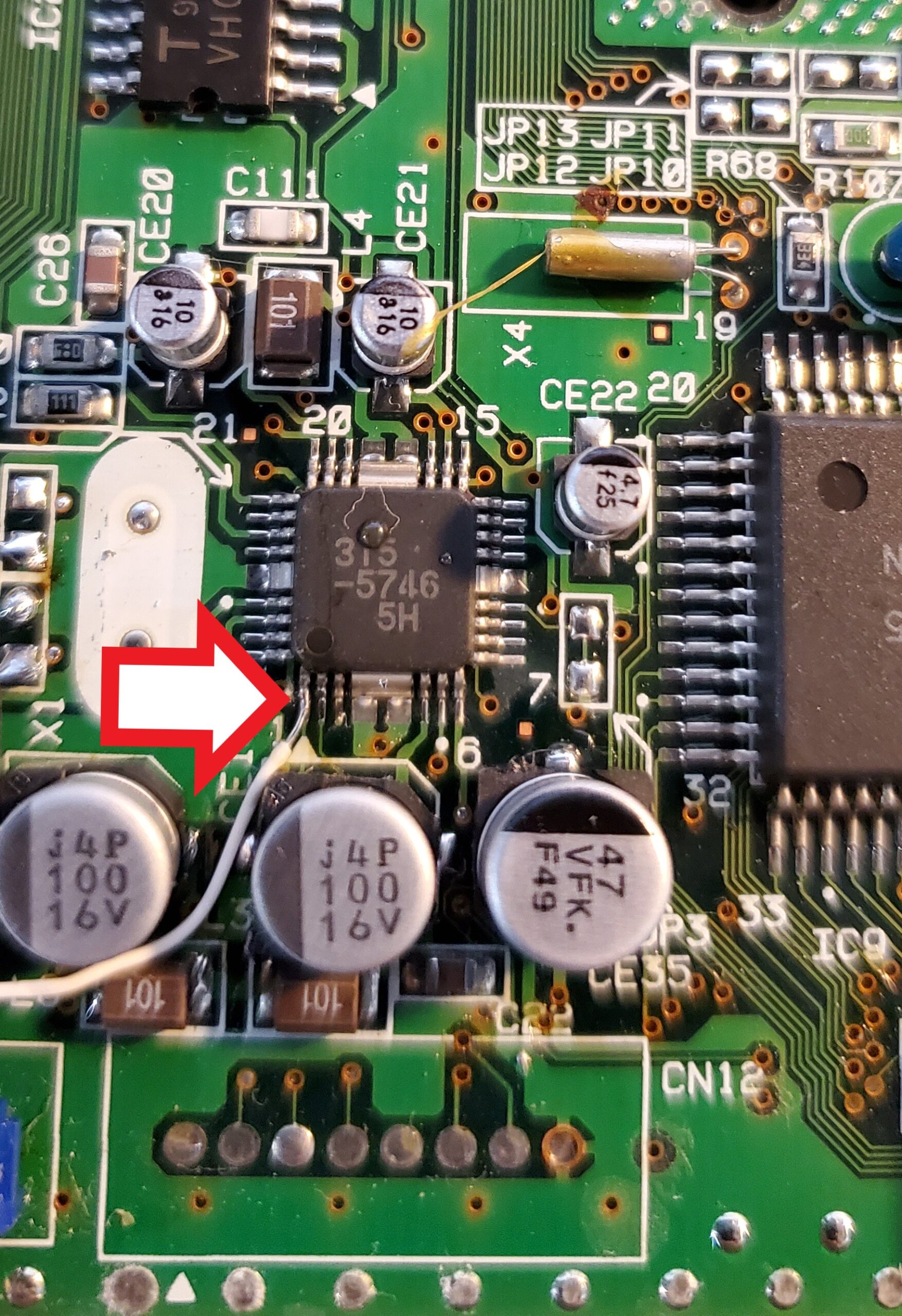
- With those connections made, you will now connect The S0-In pad on the adapter board to pin 1 of IC-20 AKA the 315-5746 chip next to where the Crystal was from the factory. See the location where the arrow is pointing to below. At this time you should also verify with a Multi-Meter that you have continuity from Pin1 of IC20 (Sega 315-5746) to Pin 79 of VDP2 (Sega 315-5690). If you do not have continuity here, you will need to also connect a wire from pin 79 of VDP2 to the S0-In pad of the adapter. If you have pin 79 lifted on your console, this is a requirement.

- If you planned on allowing switching between NTSC and PAL your final step will be making the appropriate connections to the DFO adapter board, as well as your switch or MODE.
If you are using MODE to control your system region, simply connect the S0-In pad to the Region pin of your MODE Expansion Harness and you are now done.
If you want to use a toggle switch, then you will need to connect a wire from the middle pin to S0-In, Ground to one of the outer pins, and 5V to the other outer pin.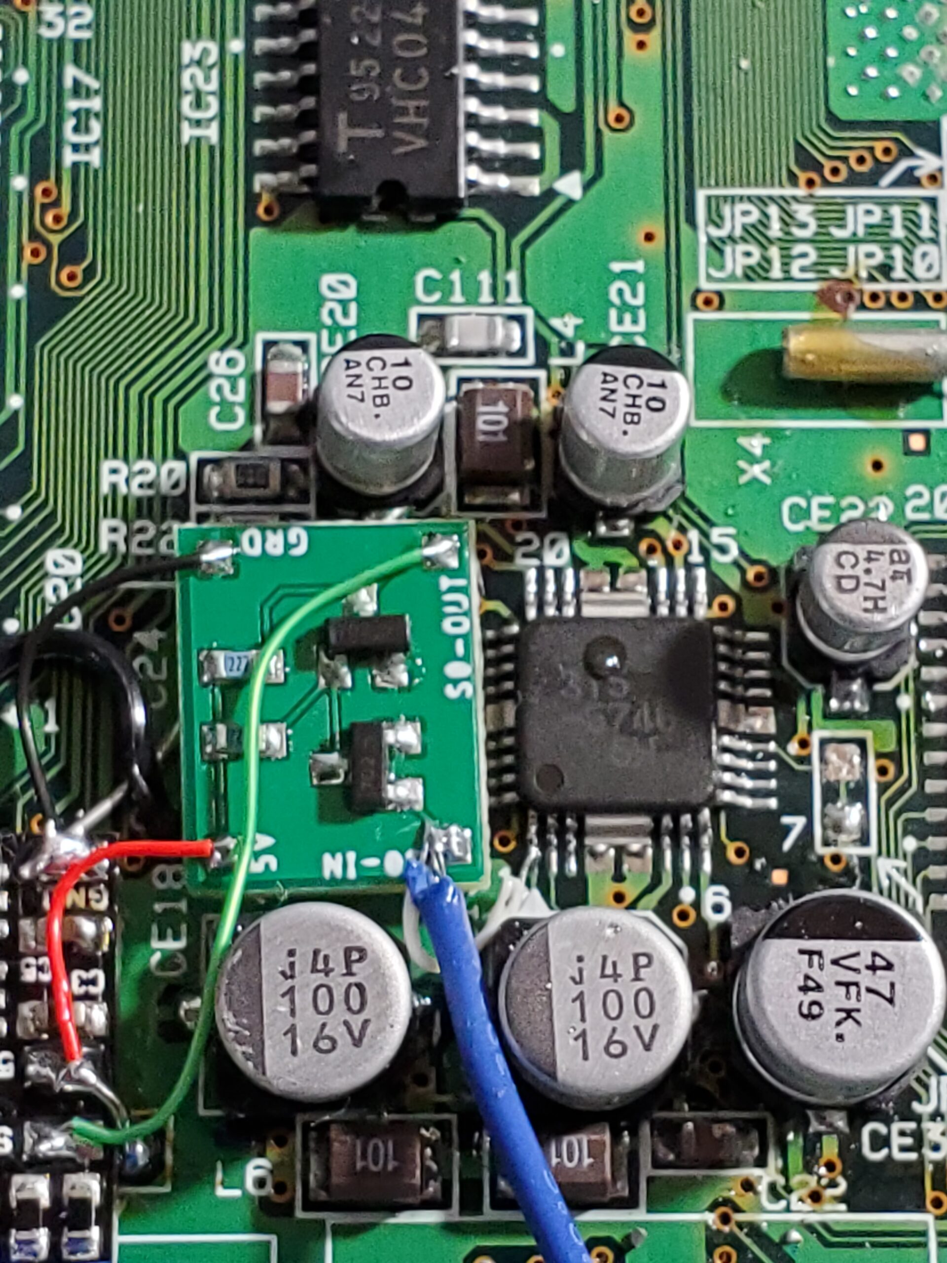
- Double-check all your connections and your installation should now be complete. Enjoy your new region or region switchable Saturn.
Troubleshooting
- When I switch refresh rates while the console is turned on, everything freezes. Is my DFO broken?
- No this is perfectly normal. The Saturn PLL does not take kindly to subcarrier frequency changes. Perform a reset and that should correct the issue. If it does not, then turn the console off and back on. This should correct this for you.
- It is best practice to only switch frequencies when the system is powered off.
- When I switch refresh rates, everything is fine but the screen rolls. Why is this happening?
- On some Sega Saturn’s you must also connect pin 7 of the Sony CXA Encoder to the S0-In pad of the adapter board. This is not common, but it does occur for some revisions.
- On some Sega Saturn’s you must also connect pin 7 of the Sony CXA Encoder to the S0-In pad of the adapter board. This is not common, but it does occur for some revisions.
- My Crystal looks different. How do I install this?
- As long as you have the Sega 315-5746 chip for IC20, you can still perform the installation. The change will be determining which pad to connect to for the CLK signal. As we perform more installations for these, we will continue to document the correct locations.
- As long as you have the Sega 315-5746 chip for IC20, you can still perform the installation. The change will be determining which pad to connect to for the CLK signal. As we perform more installations for these, we will continue to document the correct locations.
- Why do I need the adapter board? No other installs online provide or show this.
- There is a flaw in the design of the 5v DFO circuit. This flaw does not account for the weak pull-up resistor inside the CDE913 chip. Because of this, it is possible to enter into a “Three-way state” where the DFO will use an unexpected frequency. Some examples are 75hz for NTSC and 45hz for PAL. The adapter board handles this issue automatically and is provided with every Saturn DFO purchase from us.
- There is a flaw in the design of the 5v DFO circuit. This flaw does not account for the weak pull-up resistor inside the CDE913 chip. Because of this, it is possible to enter into a “Three-way state” where the DFO will use an unexpected frequency. Some examples are 75hz for NTSC and 45hz for PAL. The adapter board handles this issue automatically and is provided with every Saturn DFO purchase from us.