
Before We Begin:
Disclaimers
This document covers the DIY installation of the Dual Frequency Oscillator in a CD-i 450/550 console. Mobius Strip Technologies or any of it’s associates cannot be held responsible for any damage that occurs from the improper installation of this device. It is expected that the person performing this installation has the necessary tools and knowledge to safely do so. If you are not comfortable with electrical circuits, discharging capacitors, using basic hand tools, soldering, or working with electronic devices with high ElectroStatic Discharge sensitivity, please stop now and consult a qualified technician. You have been warned.
- It is expected that you already know how to open your CD-i console. If you are unfamiliar with this process, please seek out tutorials on disassembling your CD-i console. Please note that the documentation for this modification will feature images from CD-i 450 and CD-i 550 systems only. While compatible with other systems, some components may have different designations or locations. Please consult a service manual if you are unsure.
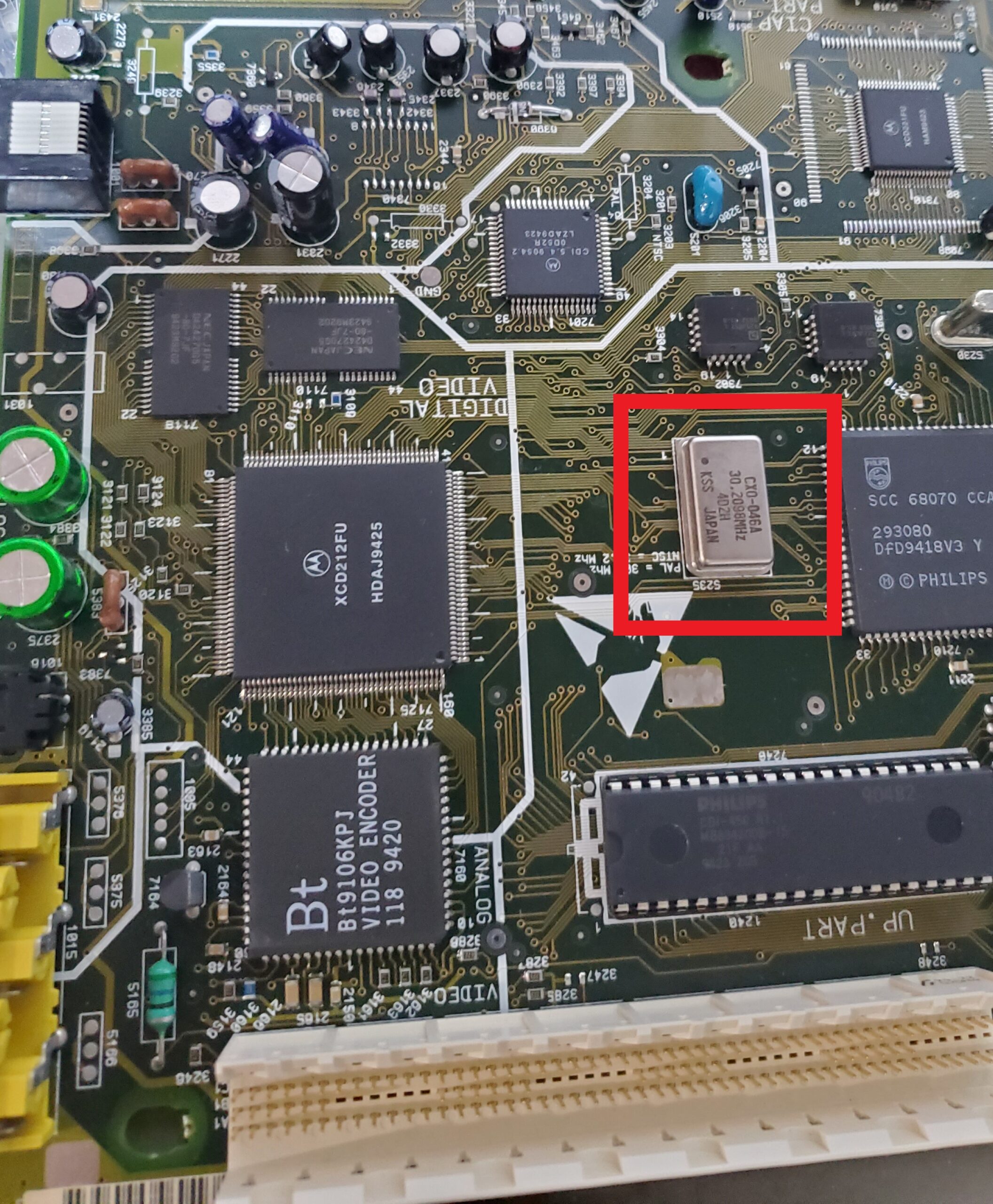
- On the main board locate the Crystal Oscillator. As seen in the red box below.

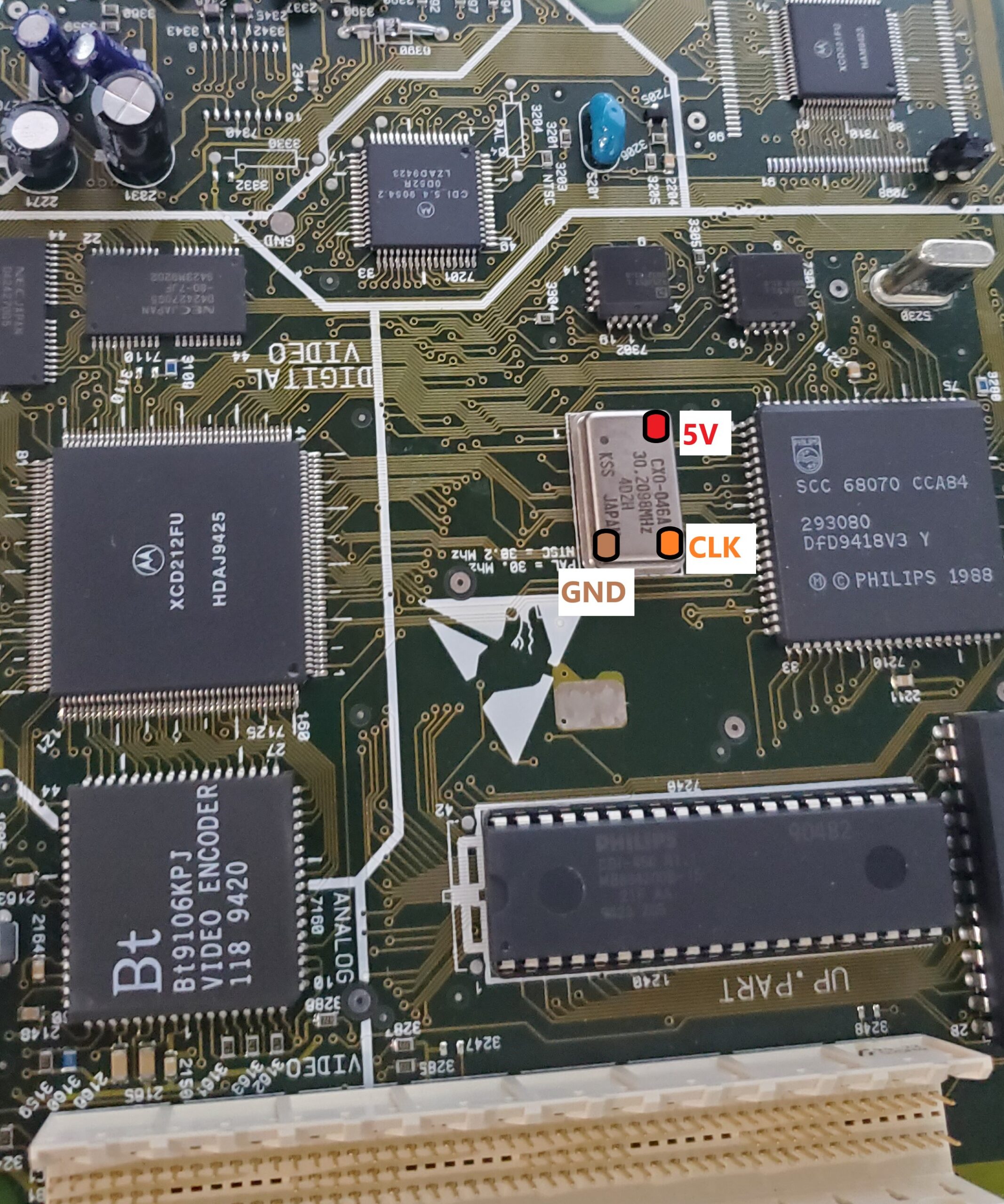
- The Crystal Oscillator will need to be desoldered from the mainboard. The points shown below will need to be connected to the corresponding points on your DFO board.

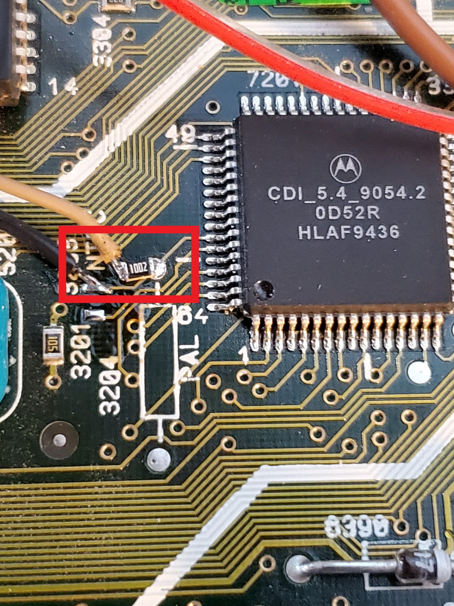
- With the DFO now connected to the points previously used for the Crystal Oscillator. You will have the S0 pad unconnected on the DFO board. Currently your console is either NTSC or PAL. However with the DFO you have the option to change that and also make it switchable. To do this locate the correct point depending on your current console and remove the resistor that sets this. If you intend on hardcoding as either NTSC or PAL, simply move the resistor from the current location to the opposite location shown below. If you intend on using a switch to allow for both NTSC/PAL, keep this resistor it will be reused in step 6.
This is the NTSC location for the resistor to remove.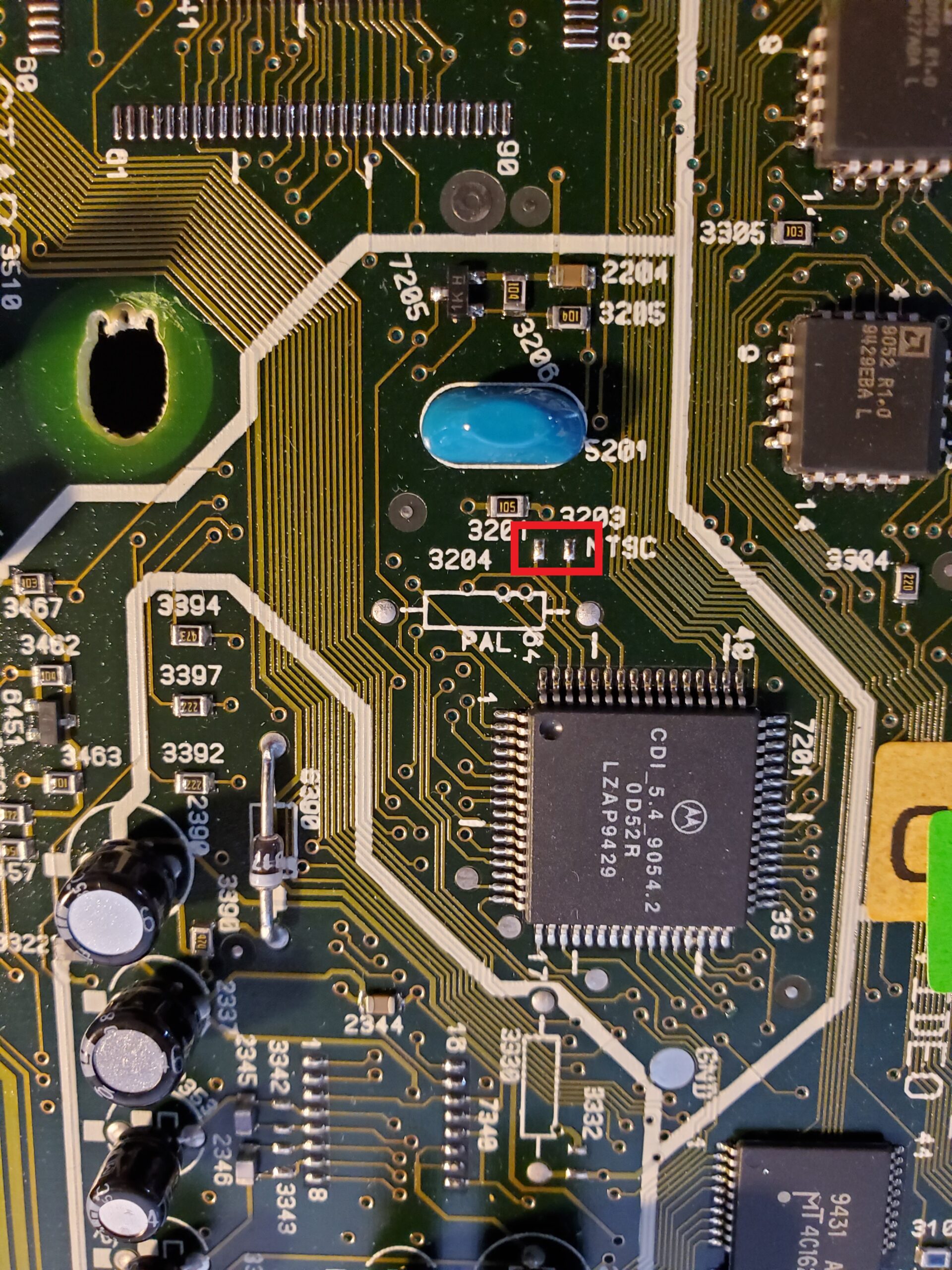

This is the location of the resistor on PAL systems. Note this is on the bottom of the board.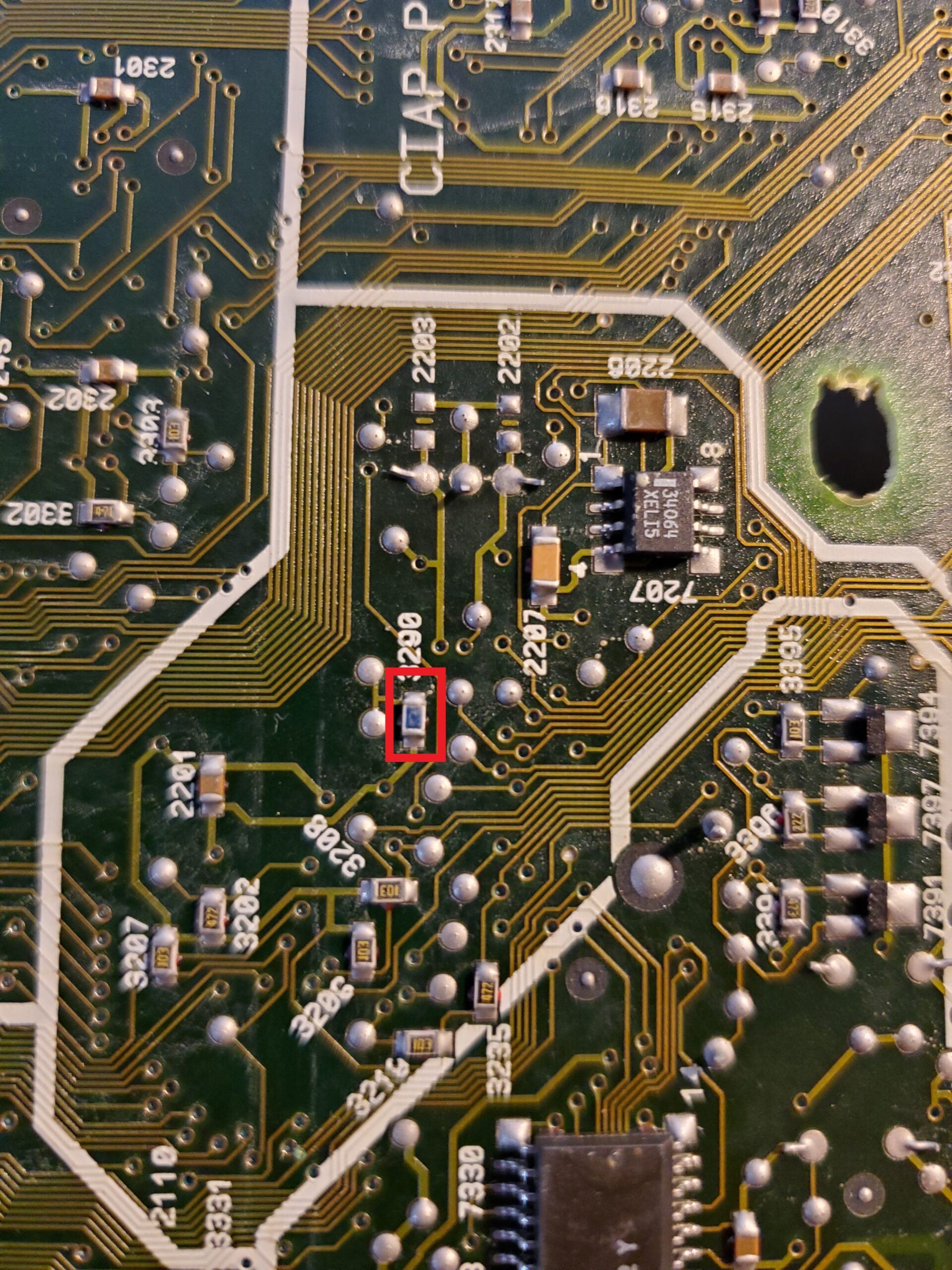
- If you intend on locking the system as either PAL or NTSC, the final step will be connecting S0 on the DFO to either Ground or 5v. You can simply run a wire from the S0 pad to the Ground or 5v pad on the DFO itself, or to any other Ground or 5v point on the console.
PAL = S0 to Ground connection
NTSC = S0 to 5v connection - If you planned on allowing switching between NTSC and PAL your final step will be making the appropriate connections to the DFO and CD-i board, as well as your switch. As seen in the picture below, connect the resistor you previously removed in step 4 to the pad in the red box. If you have lost or damaged this resistor, you can substitute with a new 10k ohms resistor. One wire will run from the resistor to the middle pin of your switch. The second wire can connect to the same pad as the 10k resistor or the open pad shown where the NTSC resistor would have been. This wire will connect to the S0 pad of the DFO. The final connections for your switch will be one side to 5v and one side to Ground. Again you can use the points on the DFO or anywhere on the board that is available.
- Double-check all your connections and your installation should now be complete. Enjoy your new region or region switchable CD-i.